Fun With Switches
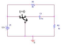
Here’s a classic problem most student hate, refer to fig. 4-1. The problem is to plot v(t) through R2 when the switch flips at t=0. Most of the time, to solve this problem, the first thing to do is to figure out v(0-), v(0+), v(Ą), and finally t. This is a tedious and time consuming task, a task that can be simplify using PSpice. Using PSpice, you will learn how to solve this type of problems.
|
|
| Fig. 4-1 – A problem the author hates |
Sec. 4.1 Preparing the schematic
- Get the voltage source, resistors, and the capacitor.
- Use VDC for the voltage source (Located in the SOURCE library)
- Resistors are located in the ANALOG library
- Capacitor are located in the ANALOG library
- For the ground, use the 0 part
- Place a Sw_Open between the voltage source and the capacitor. (Sw_Open is located in the EVAL library)
- Place a Sw_Close between the capacitor and ground. (Sw_Close is located in the EVAL library)
- Change the values for the resistors, capacitor, and voltage source as seen in fig. 4-2.
- Leave the switches in its default setting.
|
|
| Fig. 4-2 – PSpice circuit equivalent |

To simulate a switch, PSpice model it using resistors. In the Property Editor, the options that can be change are ROPEN, RCLOSED, TTRAN, TOPEN. The following is the definition from Orcad:
TOPEN=0 ; time at which switch begins to close
TTRAN=1u ; time required to switch states (must be realistic,
not 0)
RCLOSED=0.01 ; Closed state resistance
ROPEN=1Meg ; Open state resistance (Ropen/Rclosed < 1E10)
Sec. 4.2 Creating the simulation profile.
- Created a new simulation profile
- Select Time Domain (Transient) analysis.
- Set the analysis time to be greater than t.
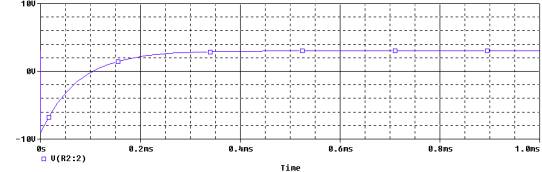
Remember t = ReqC - Simulate the circuit and view the output voltage through R2.
- The figure should look similar to fig. 4-3.
|
|
|
Fig. 4-3 – Voltage through R2 |
Fun with transformers
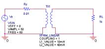
Transformers are present in most power circuits. Transformers take the voltage from the primary, and depending on the turn ratio, the secondary would either step up or step down the voltage. For this part of the lecture, you will learn how to simulate a transformer circuits, refer to fig. 4-4.
|
|
| Fig. 4-4 – Transformer circuit |
First a few thing about transformers. The equation used in PSpice to calculate the turn ratio for transformer is :
![]() , L1 and
L2 are in Henrys
, L1 and
L2 are in Henrys
In the engineering books, the primary side of the transformer should not be grounded. But for PSpice, the primary and the secondary side of the transformer must be grounded. If you do not ground the both side, PSpice would not simulate the circuit.
For the circuit in Fig. 4-4, let L1 = 10mH and L2 = 40mH, which translate to a turn ratio of 2. The input voltage is a sinewave of 50V @ 60Hz. RS is the model source resistance. RL is the resistive load.
Sec. 4.3 Setting up the schematic for the transformer circuit
- Use VSIN for the voltage source
- Set VOFF =0
- Set VAMPL = 50V
- Set FREQ = 60Hz
- The transformer is located in the ANALOG library
- Set Coupling = 1 (the value of 1 indicate an ideal transformer with no loss)
- Set L1= 10mH
- Set L2= 40mH
- The resistor is located in the ANALOG library
- Choose 0 as the ground
- Set the value of the resistors as seen in fig. 4-4.
Sec. 4.4 Setting up the profile.
- Create a new simulation profile
- Select Transient Analysis
- Set Run to Time = 17ms (That will display one cycle of the sinewave)
- Run the simulation and view the source voltage and the output voltage, refer to fig. 4-5.
|
|
|
Fig. 4-5 – The input voltage source and output voltage source. |
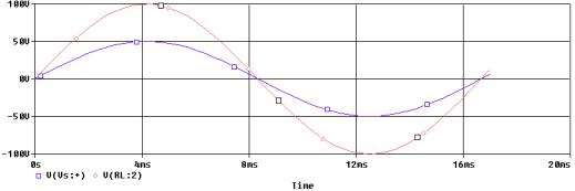
Interpreting the Results:
The input voltage source is 50Vpeak. The output voltage source is 100Vpeak. The output voltage is boost up by a factor of 2, which is also the turn ratio.